Passive Pipe Installation
Section Progress
0% Complete
Two designs may be used for passive pipe installation
- Sub-Slab Depressurization (SSD)
- Sub-Membrane Depressurization (SMD)
Vent Pipe Installation (should look almost identical to an active system)
- Main run of vent pipe (from primary suction point to exhaust)
- Minimum 3-inch in diameter
- Exteriorly 3-inch by 4-inch metal downspout may be used
- Vent pipe and fittings
- Schedule 40 PVC
- Properly joined, sealed, and air tight
- Supported every 6 feet on horizontal runs
- Supported every 8 feet on vertical runs that do not penetrate floors, ceilings or roofs
- Supported at the floor
- Installed so that any rainwater or condensation drains downward into the ground beneath the slab or soil gas retarder membrane.
Discharge Points
- At least 10’ above ground level
- At least 10’ away from or 2 feet above any opening into conditioned space
- At least 10’ from any opening into an adjacent building
- Above the highest eave of the roof and as close to the ridge line as possible
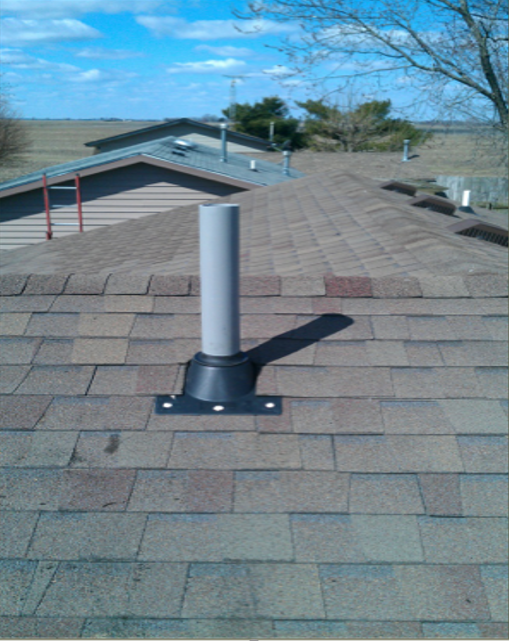
- At least 12” above surface of roof (for installations with roof penetration)
Subfloor Preparation
- A layer of gas-permeable material should be placed under all concrete slabs and other floor systems that directly contact the ground and are within the walls of the living spaces of the buildings, to facilitate future installation of a sub-slab depressurization system, if needed.
- The gas permeable layer should consist of one of the following:
- A uniform layer of clean aggregate, a minimum of 4 inches thick.
- The aggregate should consist of material that will pass through a 2 inch sieve and be retained by a ¼ inch sieve;
- A uniform layer of sand (native or fill), a minimum of 4 inches thick, overlain by a layer or strips of geo-textile drainage matting designed to allow the lateral flow of soil gases; or
- Other materials, systems or floor designs with demonstrated capability to permit depressurization across the entire subfloor area.